Code
rho = 1.25
h = 0.01
R_o = 1
V = 10
p_gauge = rho * V**2 * np.log((R_o + h)/R_o)
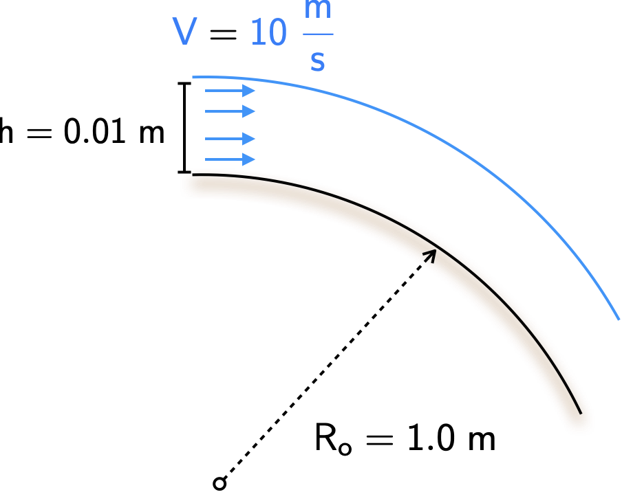
print(str(p_gauge),' Pa')1.2437913566460115 PaA jet of air is ejected tangentially onto a curved surface as shown below. Assuming that the height of the jet does not alter as it moves around the surface, and that the jet velocity is uniform across its area, please determine the gauge pressure on the solid surface. Assume the density of air is \(\require{color}{\color[rgb]{0.918231,0.469102,0.038229}\rho } = {\color[rgb]{0.918231,0.469102,0.038229}1.25 \; kg/m^3}\).
Annotating the figure above, we have:
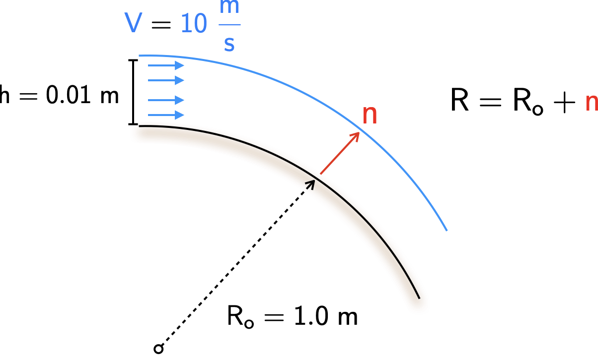
Along the curve, the pressure gradient in the normal direction is given by
\[ \large \require{color}\frac{d{\color[rgb]{0.315209,0.728565,0.037706}p}}{d{\color[rgb]{0.986252,0.007236,0.027423}n}} = {\color[rgb]{0.990448,0.502245,0.032881}\rho} \frac{{\color[rgb]{0.059472,0.501943,0.998465}V}^2}{R} \]
where the radius is given by
\[ \large \require{color}R = R_o + {\color[rgb]{0.986252,0.007236,0.027423}n}. \]
This yields
\[ \large \require{color}\frac{d{\color[rgb]{0.315209,0.728565,0.037706}p}}{d{\color[rgb]{0.986252,0.007236,0.027423}n}} ={\color[rgb]{0.990448,0.502245,0.032881} \rho}{\color[rgb]{0.059472,0.501943,0.998465} V}^2 \frac{1}{R_o + {\color[rgb]{0.986252,0.007236,0.027423}n}} \]
\[ \large \require{color}\Rightarrow d{\color[rgb]{0.315209,0.728565,0.037706}p} ={\color[rgb]{0.990448,0.502245,0.032881} \rho}{\color[rgb]{0.059472,0.501943,0.998465} V}^2 \frac{d{\color[rgb]{0.986252,0.007236,0.027423}n}}{R_o + {\color[rgb]{0.986252,0.007236,0.027423}n}}. \]
Integrating both sides, yields
\[ \large \require{color}\Rightarrow \int_{{\color[rgb]{0.315209,0.728565,0.037706}p_{surface}}}^{{\color[rgb]{0.315209,0.728565,0.037706}p_{atm}}}d{\color[rgb]{0.315209,0.728565,0.037706}p} = \int_{0}^{h} {\color[rgb]{0.990448,0.502245,0.032881} \rho}{\color[rgb]{0.059472,0.501943,0.998465} V}^2 \frac{d{\color[rgb]{0.986252,0.007236,0.027423}n}}{R_o + {\color[rgb]{0.986252,0.007236,0.027423}n}} \]
\[ \large \require{color}\Rightarrow {\color[rgb]{0.315209,0.728565,0.037706}p_{atm}} - {\color[rgb]{0.315209,0.728565,0.037706}p_{surface}} = {\color[rgb]{0.918231,0.469102,0.038229}\rho} {\color[rgb]{0.059472,0.501943,0.998465}V}^2 ln \left( \frac{R_o + h}{R_o} \right) \]
Recognizing that the left hand side is the gauge pressure, we can now go ahead and plug in the numerical values.rho = 1.25
h = 0.01
R_o = 1
V = 10
p_gauge = rho * V**2 * np.log((R_o + h)/R_o)
print(str(p_gauge),' Pa')1.2437913566460115 PaConsider the following qualitative queries:
Curved streamlines are indicative of a pressure gradient, i.e., with higher pressure lying away from the center of curvature. This is why the pressure towards the center of a cyclone is lower than the pressure that lies outward.
It is incorrect to assume that the air in the jet has the same Bernoulli constant as the surrounding ambient air. In fact, assuming the static pressure of the jet leaving the mouth is the same as the ambient pressure, then there is a difference of \(\require{color}\{\color[rgb]{0.918231,0.469102,0.038229}rho} {\color[rgb]{0.059472,0.501943,0.998465}v}^2 / 2\) between the two.
The paper lifts owing to the Coanda effect.
The Magnus effect is observed on rotating cylinders or spheres. A pressure difference across a rotating body is formed which leads to a normal force, generating lift (depending on the direction of rotation). Some examples include spinning golf and baseballs.
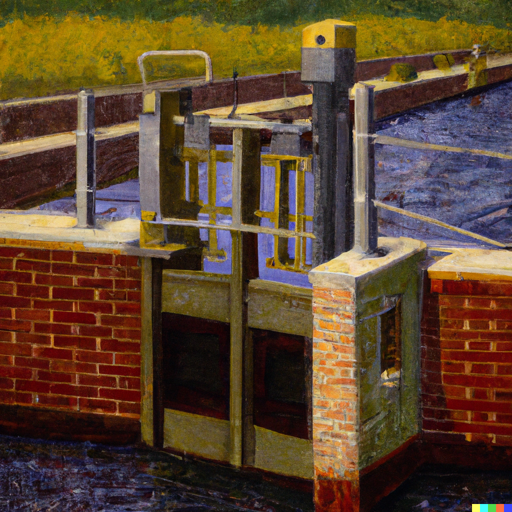
Water flow in open channels can be controlled and measured with the sluice gate shown below. The flow is uniform at a moderate distance upstream and downstream of the gate, i.e. at sections 1 and 2. Consider the following two questions:
\[ \large \require{color}{\color[rgb]{0.986252,0.007236,0.027423}F} = {\color[rgb]{0.918231,0.469102,0.038229}\rho }{\color[rgb]{0.059472,0.501943,0.998465}V_1}^2 h_1 - {\color[rgb]{0.918231,0.469102,0.038229}\rho}{\color[rgb]{0.059472,0.501943,0.998465}V_2}^2 h_2 + \frac{{\color[rgb]{0.918231,0.469102,0.038229}\rho} g h_1^2}{2} - \frac{{\color[rgb]{0.918231,0.469102,0.038229}\rho} g h_2^2}{2}. \]
| Sluice gate | Schematic |
|---|---|
 |
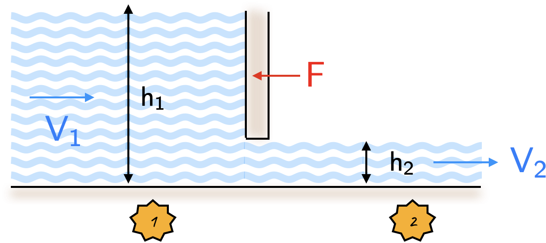 |
It will be useful to consider a control volume around stations 1 and 2. From the steady flow momentum equation along the horizontal direction we have
\[ \large \require{color}\sum F + \sum {\color[rgb]{0.315209,0.728565,0.037706}p}A = \sum \dot{m}_{out} {\color[rgb]{0.059472,0.501943,0.998465}v_{out}} - \sum \dot{m}_{in}{\color[rgb]{0.059472,0.501943,0.998465} v_{in}} \]
Thus we have
\[ \large \require{color}{\color[rgb]{0.986252,0.007236,0.027423}F}_{fluid} + \int_{0}^{h_1} {\color[rgb]{0.315209,0.728565,0.037706}p_1} d{\color[rgb]{0.131302,0.999697,0.023594}y} - \int_{0}^{h_1} {\color[rgb]{0.315209,0.728565,0.037706}p_2} d{\color[rgb]{0.131302,0.999697,0.023594}y} = {\color[rgb]{0.918231,0.469102,0.038229}\rho} h_2 {\color[rgb]{0.059472,0.501943,0.998465}v_2} {\color[rgb]{0.059472,0.501943,0.998465}v_2} - {\color[rgb]{0.918231,0.469102,0.038229}\rho} h_1 {\color[rgb]{0.059472,0.501943,0.998465}v_1 v_1} \]
\[ \large \require{color}\Rightarrow{\color[rgb]{0.986252,0.007236,0.027423}F}_{fluid} = -\int_{0}^{h_1} {\color[rgb]{0.315209,0.728565,0.037706}p_1} d{\color[rgb]{0.131302,0.999697,0.023594}y} +\int_{0}^{h_1} {\color[rgb]{0.315209,0.728565,0.037706}p_2} d{\color[rgb]{0.131302,0.999697,0.023594}y} + {\color[rgb]{0.918231,0.469102,0.038229}\rho} h_2 {\color[rgb]{0.059472,0.501943,0.998465}v_2}^2 - {\color[rgb]{0.918231,0.469102,0.038229}\rho} h_1 {\color[rgb]{0.059472,0.501943,0.998465}v_1}^2 \]
where the force on the fluid, \(\require{color}{\color[rgb]{0.986252,0.007236,0.027423}F}_{fluid}\) acts in the positive \(x-\)direction. This is opposite to the force acting on the gate.
Now, note the assumptions we have made: - velocities at 1 and 2 are uniform; - conditions are steady on average; - shear stress (fluid friction) may be ignored.
Now we need to find the pressure forces at entry and exit, i.e., \({\color[rgb]{0.315209,0.728565,0.037706}p_1}\) and \({\color[rgb]{0.315209,0.728565,0.037706}p_2}\). The streamlines at 1 and 2 are parallel, so there is no centripetal acceleration. Thus, the vertical pressure gradient balances the gravitational force. In other words, we have hydrostatic balance. Thus we have
\[ \large \require{color}{\color[rgb]{0.315209,0.728565,0.037706}p_1} ={\color[rgb]{0.918231,0.469102,0.038229} \rho} g \left(h_1 - {\color[rgb]{0.131302,0.999697,0.023594}y }\right), \; \; \; \; {\color[rgb]{0.315209,0.728565,0.037706}p_2} ={\color[rgb]{0.918231,0.469102,0.038229} \rho} g \left(h_2 - {\color[rgb]{0.131302,0.999697,0.023594}y }\right). \]
Computing the integrals (the terms from above), yields
\[ \large \require{color}\Rightarrow \int_{0}^{h_1} {\color[rgb]{0.315209,0.728565,0.037706}p_1} d{\color[rgb]{0.131302,0.999697,0.023594}y} = \frac{1}{2}{\color[rgb]{0.918231,0.469102,0.038229}\rho} g h_1^2, \; \; \; \; \Rightarrow \int_{0}^{h_2} {\color[rgb]{0.315209,0.728565,0.037706}p_2} d{\color[rgb]{0.131302,0.999697,0.023594}y} = \frac{1}{2}{\color[rgb]{0.918231,0.469102,0.038229}\rho} g h_2^2 \]
Thus we can combine the above to work out the force acting on the fluid, i.e.,
\[ \large \require{color}\Rightarrow{\color[rgb]{0.986252,0.007236,0.027423}F}_{fluid} = -\frac{1}{2}{\color[rgb]{0.918231,0.469102,0.038229}\rho} g h_1^2 + \frac{1}{2}{\color[rgb]{0.918231,0.469102,0.038229}\rho} g h_2^2 + {\color[rgb]{0.918231,0.469102,0.038229}\rho} h_2 {\color[rgb]{0.059472,0.501943,0.998465}v_2}^2 - {\color[rgb]{0.918231,0.469102,0.038229}\rho} h_1 {\color[rgb]{0.059472,0.501943,0.998465}v_1}^2. \]
The force acting on the gate is equal to the opposite, i.e.,
\[ \large \require{color}\Rightarrow{\color[rgb]{0.986252,0.007236,0.027423}F} = \frac{1}{2}{\color[rgb]{0.918231,0.469102,0.038229}\rho} g h_1^2 - \frac{1}{2}{\color[rgb]{0.918231,0.469102,0.038229}\rho} g h_2^2 - {\color[rgb]{0.918231,0.469102,0.038229}\rho} h_2 {\color[rgb]{0.059472,0.501943,0.998465}v_2}^2 + {\color[rgb]{0.918231,0.469102,0.038229}\rho} h_1 {\color[rgb]{0.059472,0.501943,0.998465}v_1}^2. \]